

Cordless Power Tools – Are you ready to cut the (power) cord?
By Ed Truxal, BN Products-USA™ Can you really cut the cord today on heavy-duty construction tools? Remember the first cordless drill that you – or perhaps your parents – had? It was large, heavy, and the battery certainly would not have lasted as long as the new one you might buy today at any local Read more…
Inverter Generators: Evolution of Portable Power
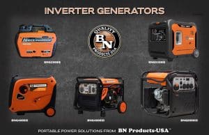
While the future of portable power solutions is exciting – notably less-dependent upon fossil fuels, and harnessing more sources of clean energy – generator technology has also advanced greatly in recent decades. Most notably, the need to power sensitive electronics and to operate with greater efficiency has advanced the distinction between traditional gas, diesel, or propane-powered generators, and safer, more-efficient power plants – known as Inverter Generators.
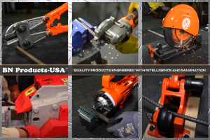
Superior Demolition Power on the Job Site
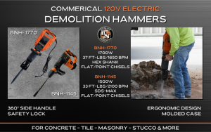
BN Products USA™ Unveils New Line of Demolition Tools By: Mike Shubic of MikesRoadTrip.com – A BN Products-USA™ Contributor Demolition work is a fundamental part of the construction industry. It involves the dismantling of buildings and structures, and to accomplish this, specialized tools are necessary. Among these tools, demolition hammers, typically known as jackhammers, are Read more…
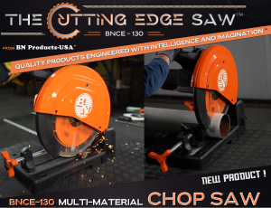
Cut Smarter, Not Harder: Introducing the Innovative BNCE-130 Cutting Edge™ Chop Saw
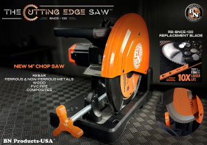
By Mike Shubic – BN Products-USA™ Contributor The Ultimate Cutting Tool Has Arrived: Meet the Brand New BNCE-130 Cutting Edge™ Chop Saw BN Products USA is proud to introduce the brand BNCE-130 Cutting Edge™ Chop Saw, the tool that every professional and DIY enthusiast needs in their arsenal. BNProducts-USA™ has revolutionized the way materials are Read more…
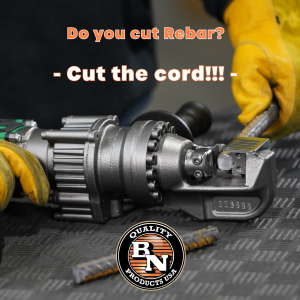
30 Tools to Cut Rebar (and still do it right!)
Cutting rebar is an essential task in any construction project that involves reinforced concrete. With the right tools, you can ensure that the job is done safely and efficiently. In this article, we will discuss the different rebar cutting tools from BN Products USA and how they can help you get the job done right. Read more…
Cold-Saw Innovation: The Cutting Edge™ Chop Saw
Looking at the future of the Cutting Edge Saw™ by BN Products-USA™ By Ed Truxal, BN Products-USA™ Cold-cutting metal saws are certainly nothing new in the power tools market or the construction industry. For decades, slower-RPM saws of varied shapes and sizes have been used to cut pipe, conduit, threaded rod, and rebar with precision, Read more…
A Contractor’s Key to Profit: Art of the Estimate
vCalc.com is a FREE website featuring hundreds of calculators, and thousands of equations created by engineers, university professors, students from around the world, and practical people like you. Topics range from complex scientific equations to useful, everyday, calculated solutions. For the contractor, vCalc’s tools provide highly accurate mathematical solutions to help you estimate the volume Read more…
Concrete Form Safety Tools
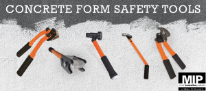
Installation and removal of concrete forms can be a back-breaking and sometimes dangerous job. Whether you are driving stakes or pulling duplex nails and stakes on the job site, BN Products USA has introduced a tool set that makes the tasks far easier and safer for the contractor. Our tools provide the means to hold Read more…